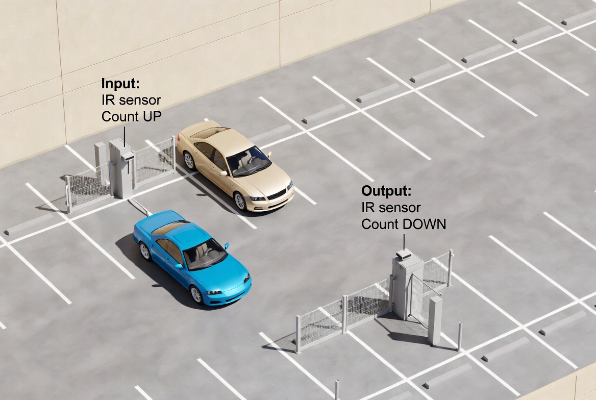
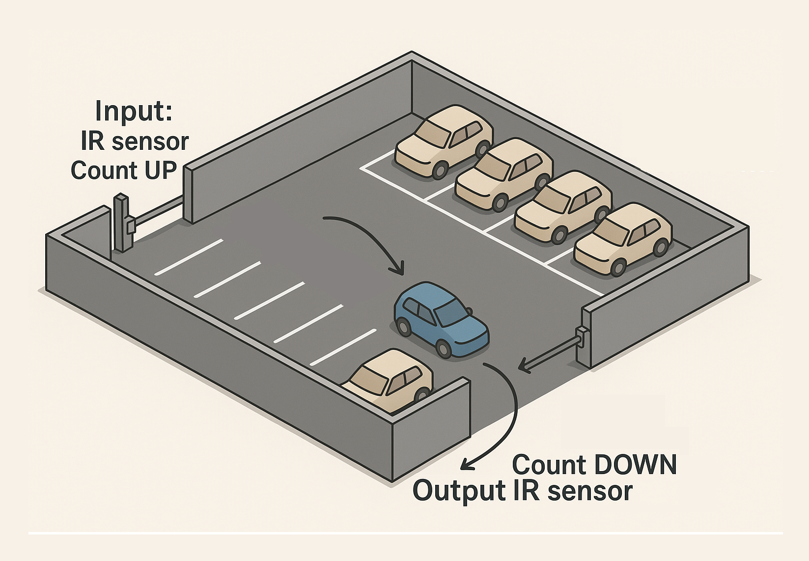
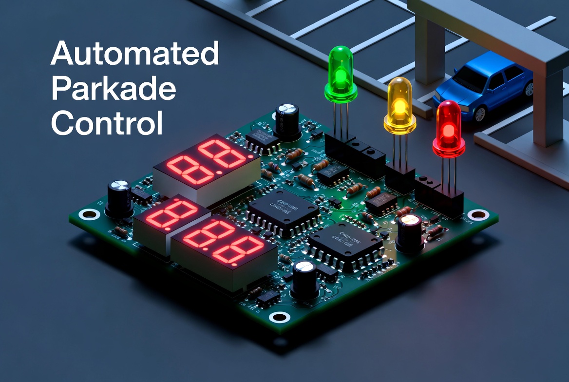
Parkade Counter
Technical Architecture

System Overview

This page ties the whole project together. It sits between the landing page and the detailed stage pages, using the supplied diagrams and PDFs to show how the parkade counter moves from vehicle sensing to display logic and finally to warning-state control.

Top-Level Flow

System Signal Path

The logic path is simple by design: entry and exit sensors create pulses, the counter chain stores occupancy, and the decoded output drives the green, yellow, or flashing red state.
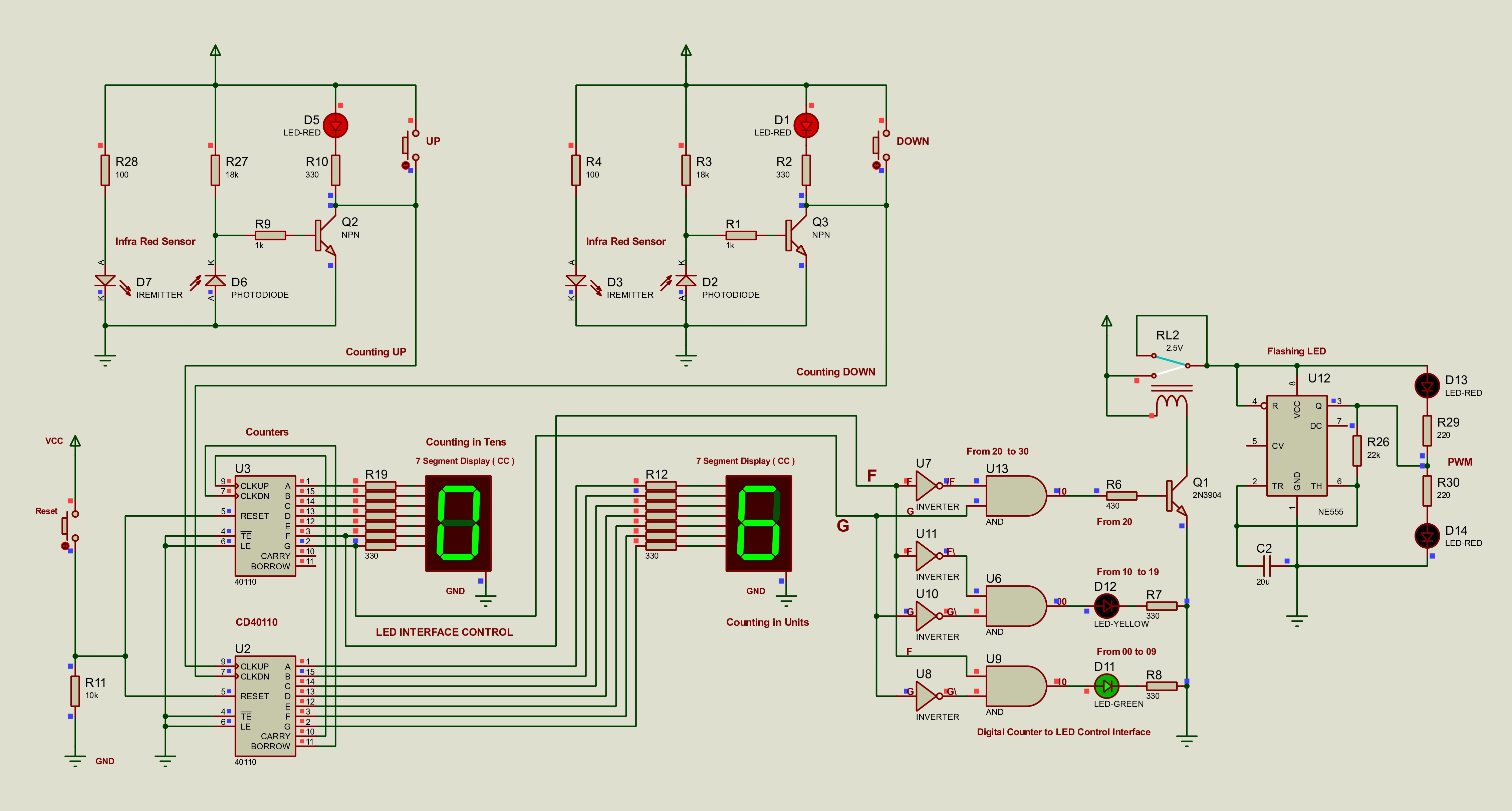
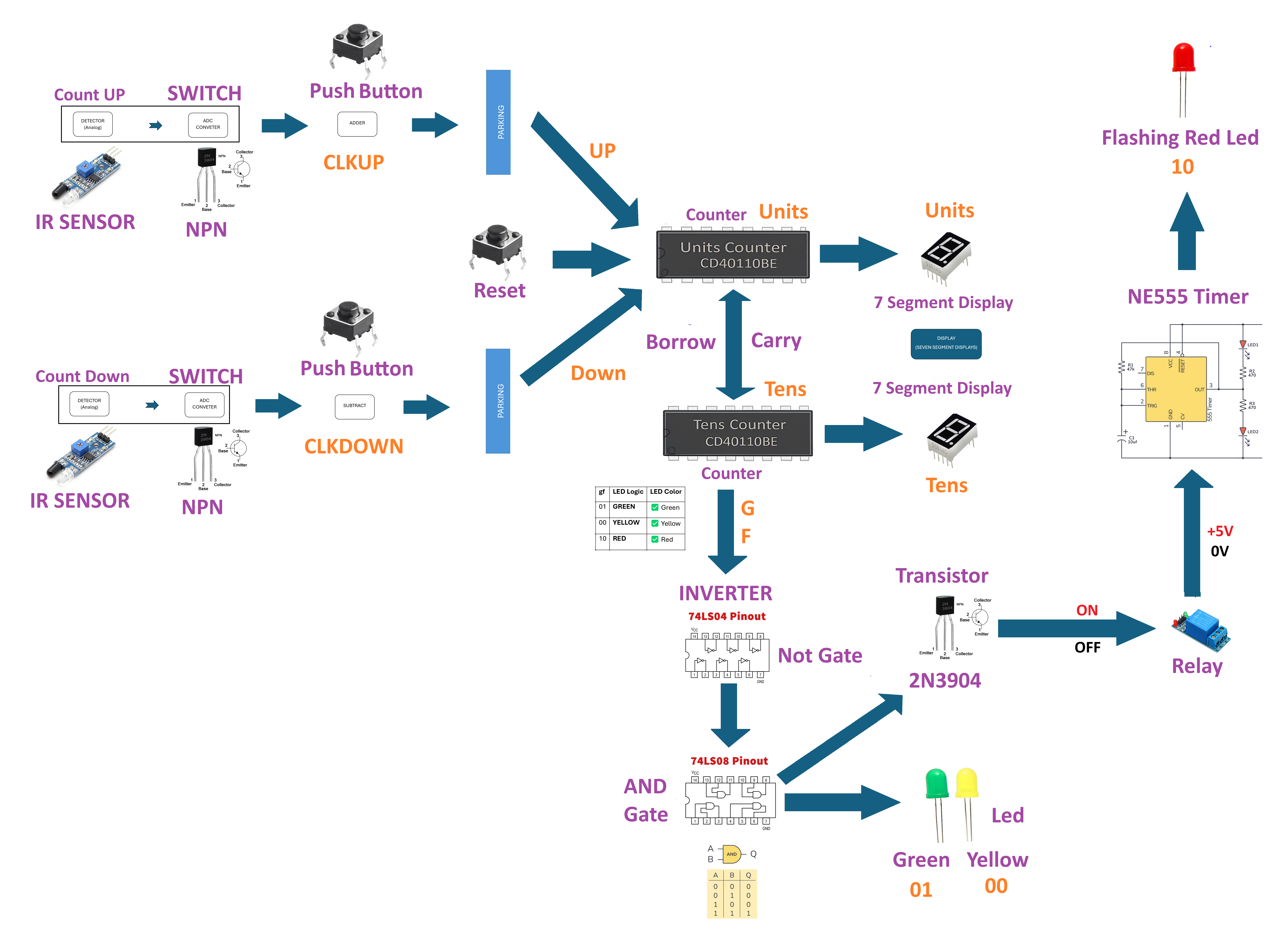
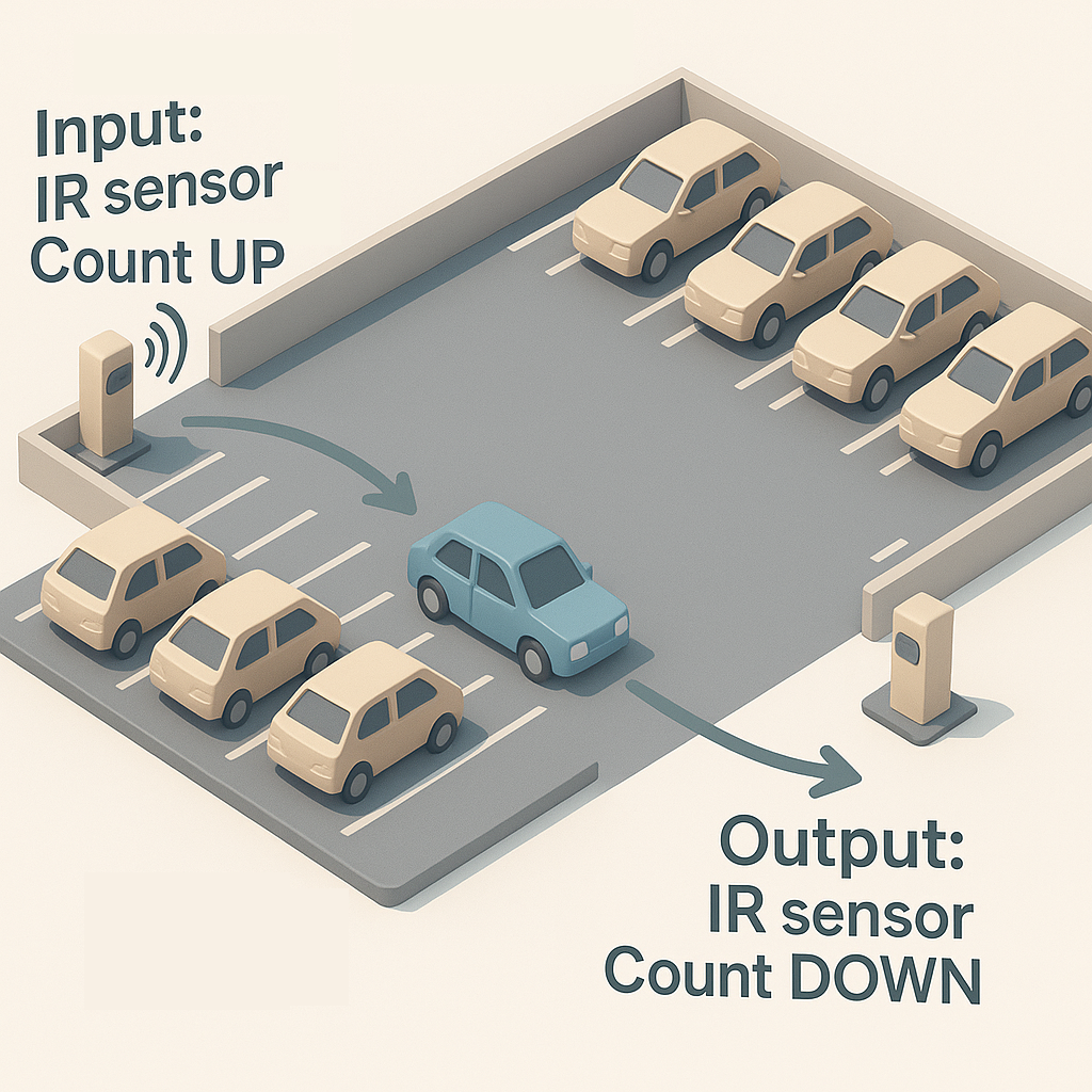
High-resolution entry and exit sensor concept render from the supplied image folder
High-resolution concept render from the supplied image folder. The technical block diagram remains in the reference views below.

Detector Interface

Stage 1 produces the clock-up and clock-down events. The brief explicitly encourages designing and testing this analog front end on its own before building the rest of the circuit.
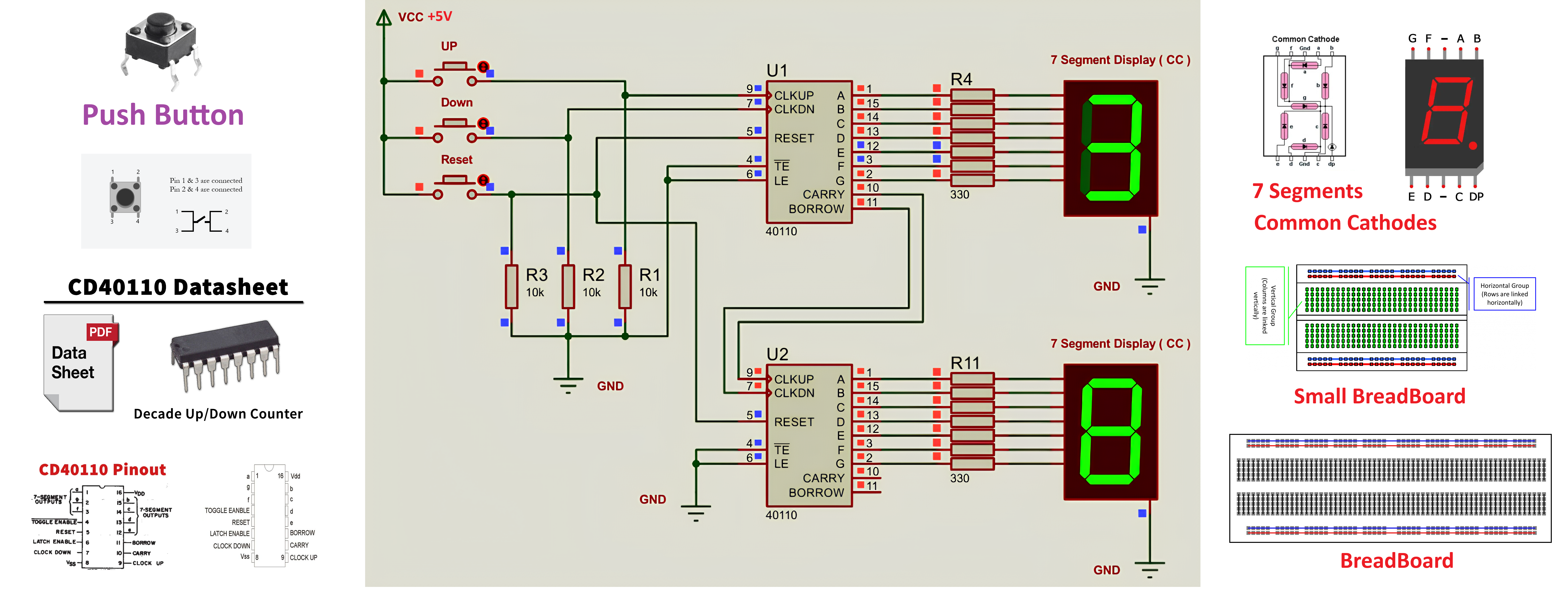
Counter Chain

Two CD40110BE devices handle the occupancy value and feed the two seven-segment displays. This keeps the entire design in discrete electronics with no firmware dependency.

Status Decode

The tens counter outputs feed 74LS04 and 74LS08 logic. Those outputs decide whether the system is in normal, warning, or full state.

Isolation Requirement

The NE555 warning path must be isolated through the transistor and relay. That is one of the most important practical constraints in the brief and the notes.

Reference Views

Core Visual References

These views are the fastest way to understand the system without opening the detailed gallery page.

Parking lot sensor layout diagram Full system schematic System partition overview Counter stage diagram Parkade control render Concept board render
Document Set

Linked Project Files

The supplied PDFs are available locally so the design requirements and shopping references sit next to the visual material.

Brief
Assignment Specification
Formal project brief describing the staged engineering workflow, evaluation structure, and core operating rules for the control system.
Partition
Project Partition Sheet
Compact partition document listing the complete simulation, stage 1, stage 2, and stage 3 breakdown used throughout the rest of the stitch pages.
BOM
Component Purchase Sheet
Cape Town sourcing sheet with price estimates and part references for the components that matter most to the final physical build.