Parkade Counter
Circuit Breakdown

Three Circuit Stages

The site uses the same three-stage structure required by the project brief: detector input, counter display logic, and LED status control. Each section below is paired with the supplied diagram assets so the written explanation and the schematic view stay together.

Stage 1 detector diagram
Stage 1 diagram from the provided image set.
Stage 01

Input And Output Parking Detector

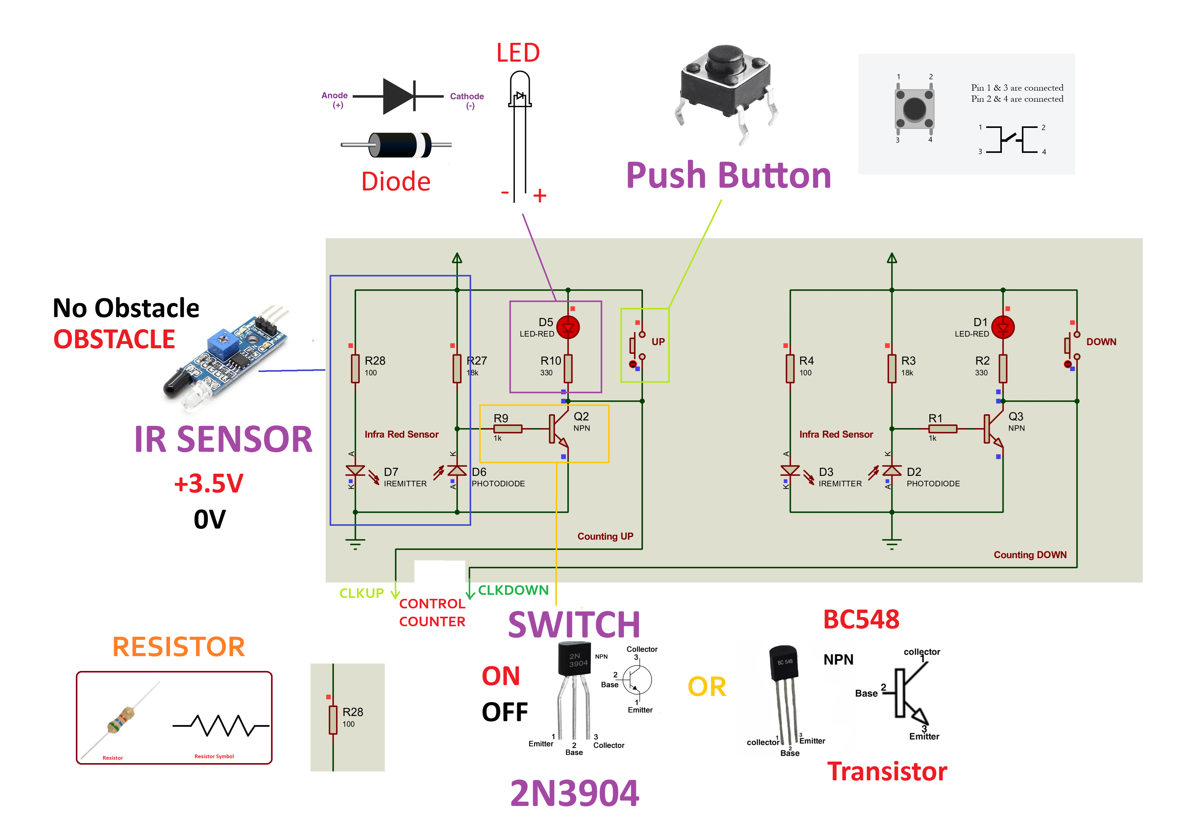
Two custom-built IR sensing paths detect vehicle entry and exit at the parking gates. In the physical build the TCRT5000 module is used, while in Proteus the detector is represented with an IREMITTER and PHOTODIODE pair plus transistor conditioning.

When an obstacle is present the conditioned output rises and triggers either the count-up or count-down input. Manual push buttons are included so the circuit can be tested and reset without depending only on the optical path.

Use the Proteus workaround for the education license: IREMITTER plus PHOTODIODE rather than a full prebuilt IR module. Keep the analog conditioning stage separate before moving into the counter inputs.
TCRT5000 x2 2N3904 x2 BC548 option Push buttons 330 ohm / 1k / 18k
Stage 2 counter and display diagram
Stage 2 counter and display view from the provided diagrams.
Stage 02

Counter And Display Interface

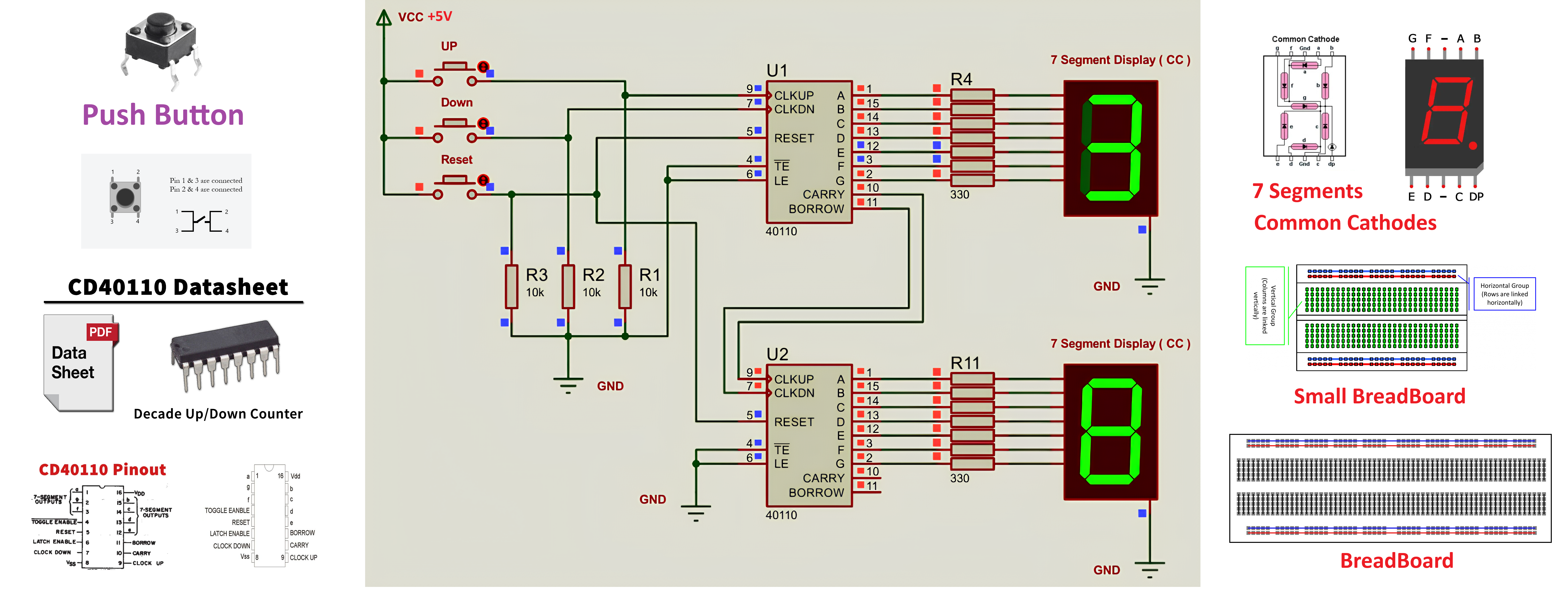
Two CD40110BE decade up/down counters are cascaded with carry and borrow links so the circuit can display occupancy from 0 to 20. The units display handles the first digit and the tens display changes as capacity rises toward the full state.

Each display segment requires its own current-limiting resistor and the displays must be common cathode devices. Pull-down resistors on CLKUP, CLKDN, and RESET keep the logic stable when no signal is present.

Use common cathode displays only. Do not substitute common anode devices. The CD40110BE is a specialist IC, so confirm stock with Communica before visiting.
CD40110BE x2 CC 7-segment x2 330 ohm x14 10k pull-down x3 Reset button
Stage 3 LED status control diagram
Stage 3 LED control and NE555 flashing stage.
Stage 03

LED Status Control Interface
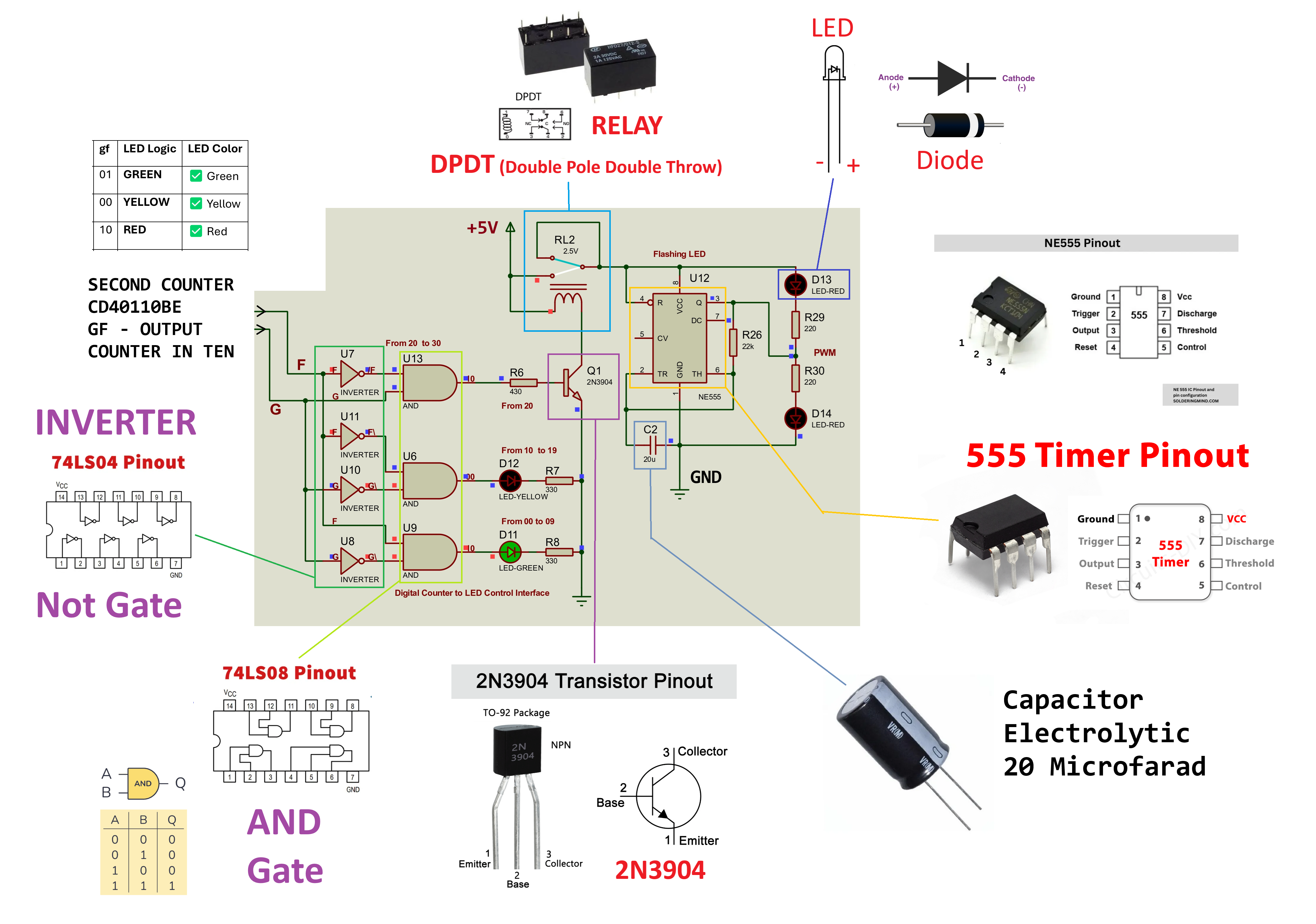
The tens counter outputs feed a 74LS04 inverter and 74LS08 AND gate network to decode the occupancy state into green, yellow, or full-capacity red. The final red indicator is not driven directly from the counter output.

Instead, a transistor and DPDT relay isolate the logic from an NE555 astable timer. That separation protects the counter stage while enabling a visible flashing warning at the 20-car full condition.

Do not connect the NE555 directly to the counter output. Use the transistor, relay, and flyback diode so the timer remains electrically isolated from the decoding logic.
Recommended flashing setup: 22k ohm resistor with 20uF capacitor for roughly a 1Hz flashing rate. Use a 5V relay coil and place a 1N4148 diode across the coil.
74LS04 x1 74LS08 x1 NE555 x1 DPDT relay 5V 2N3904 1N4148
Output States

LED Status Logic

The final decoded output state is easy to test in the browser demo and easy to verify in the circuit diagrams.

Green
Count 0 to 9
Normal operating range with parking still available.
gf = 01
G = 0, F = 1
Yellow
Count 10 to 19
Warning range showing the system is filling up toward the maximum capacity.
gf = 00
decoded through inverter logic
Flashing Red
Count 20
Full-capacity state with relay-switched NE555 flashing warning output.
gf = 10
relay + NE555 active