Parkade Counter
Stage 02 Files

Counter And Display

This page keeps the Stage 2 counter material together: one-counter validation, counter display wiring, the base two-counter display chain, the new Version 2 to Version 4 alternatives, the combined Version 3 and 4 comparison project, the new Stage 2 plus Stage 3 bridge packs, the linked Day 3 walkthrough, and the relevant CD40110BE display reference images.

Two Counter Display Proteus preview
CD40110BE x2 Dual-Digit Count Common Cathode Carry / Borrow
Stage Purpose
Count Cars And Drive Displays
Stage 2 receives the count-up and count-down pulses from Stage 1 and converts them into a visible parking count. The early files validate the first digit and the base dual-digit chain, while Version 2, Version 3, and Version 4 compare mixed, common-cathode, and common-anode decoder/display pairings. The newer combined files also preserve the Version 3 and Version 4 comparison in one project and the handoff from Stage 2 into Stage 3 through both bridge packs.
Match the decoder and display type to the version you open. The original checkpoints use the base common-cathode flow, the alternative versions compare different decoder/display pairings, and the combined project files add side-by-side and bridge testing.
The newer full-system package still extends the Stage 2 count to a complete 00-to-30 cycle and resets when the display reaches 30. Use the Day 3 walkthrough, the Stage 3 page, and the Complete Circuit page for the later integrated versions.
Stage 2 Resource Pack

Proteus Files And Exports

The counter files are grouped from the earliest one-counter checkpoint through the full two-counter display project, then into the newer Stage 2 decoder/display variants, the combined Version 3 and Version 4 comparison pack, and the Stage 2 plus Stage 3 bridge projects.

Counter 01
One Counter Checkpoint
Single counter validation set for proving the first CD40110BE and display before cascading the second digit.
Counter 02
Counter Display Checkpoint
Display wiring checkpoint for verifying the segment outputs, current-limiting resistors, and common cathode display behavior.
Counter 03
Two Counter Display
Full Stage 2 display-chain package with the two-counter Proteus project, exported PDF, and supplied preview image.
Counter 04
Stage 2 Version 2 - Mixed Counter TL
Alternative Stage 2 version using a common anode decoder path with a common cathode display arrangement.
Counter 05
Stage 2 Version 3 - Stage2-V2
Alternative Stage 2 version using a common cathode decoder together with a common cathode display.
Counter 06
Stage 2 Version 4 - Stage2-V3
Alternative Stage 2 version using a common anode decoder together with a common anode display.
Counter 07
New Counter TL - Versions 3 And 4 Together
Combined Stage 2 comparison project that keeps Version 3 and Version 4 together in one Proteus file for side-by-side checking.
Counter 08
New Project - Stage 2 And Stage 3
Combined project that links the Stage 2 counter chain directly into the Stage 3 LED control interface for handoff testing.
Counter 09
Question8 - New Stage 2 And Stage 3
Updated combined project showing the new Stage 2 counter section and new Stage 3 LED logic working together in one Proteus file.
Counter Notes

Stage 2 Wiring Checks

Use these checks when rebuilding the circuit from the Proteus files.
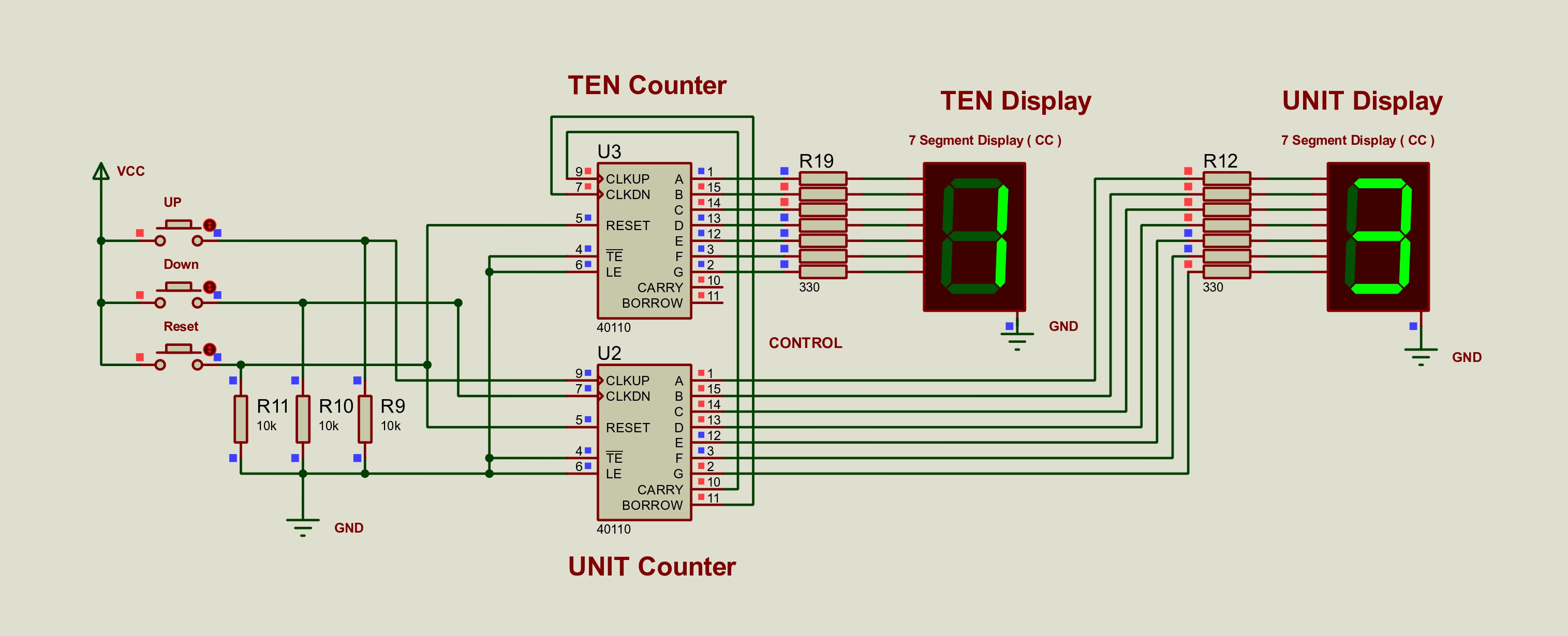
Counter Inputs

CLKUP and CLKDN should receive clean pulses from the Stage 1 detector outputs. Pull-down resistors keep the inputs stable when no car is detected.

Display Type

Match the display and decoder style to the version you open. This page now includes the base common-cathode chain, a mixed anode-to-cathode version, a cathode-to-cathode version, an anode-to-anode version, and the combined comparison pack for Versions 3 and 4.

Cascade Behavior

The carry and borrow links between counters allow the display to move from the units digit into the tens digit across each variant. The newer bridge projects then carry that Stage 2 output forward into the Stage 3 LED logic section.

Visual References

Counter Images

These images support the Stage 2 display and counter wiring, including the newer mixed, cathode, anode, combined comparison, and Stage 2 to Stage 3 bridge builds.

Stage 2
Counter Diagram
The polished counter and display view used across the site.
Checkpoint
One Counter Preview
Single-counter checkpoint before the second digit is added.
Version 2
Mixed Counter TL
Alternative Stage 2 build using a mixed decoder/display pairing.
Version 3
Stage2-V2 Preview
Cathode-to-cathode Stage 2 comparison build.
Version 4
Stage2-V3 Preview
Anode-to-anode Stage 2 comparison build.
Combined
New Counter TL
Version 3 and Version 4 preserved together in one comparison project.
Bridge
Stage 2 + Stage 3
Combined project linking the counter display outputs into the LED control interface.
Bridge 02
Question8 Preview
Updated bridge build where the newer Stage 2 and Stage 3 sections are checked together.
Reference
Part 2 Sheet
Large-format counter and display reference image from the high-quality pack.
Next Stage

Continue The Build