Parkade Counter
Integrated Simulation

Complete Circuitry

This page is for the supplied full Proteus circuit where the new Stage 1 IR input, the newer Stage 2 counter display chain, and the Stage 3 LED status logic are combined into one complete simulation that counts from 00 to 30 and then resets at 30.

Final Project integrated Proteus simulation preview
New IR Input New Stage 2 Chain Stage 3 LED Logic 00 To 30 Count Reset At 30
Complete File Set
Final Project Integrated System
Use this supplied file set when you want the latest combined project instead of the separate Stage 1, Stage 2, and Stage 3 checkpoint files. It is the integrated simulation for the complete parkade counter using the new IR input and the newer Stage 2 path, counting from 00 to 30 and resetting at 30.
Keep the individual stage pages for debugging. Use this complete page when checking the final signal flow from the new IR detector input through the updated display count, flashing warning, and reset action at 30. The earlier first-method complete pack and the mixed comparison pack with new Stage 1 plus older Stage 2 and Stage 3 are both preserved below for comparison.
Required Files

Complete Circuit Downloads

These are the exact complete-circuit files from the supplied Proteus folder, with the newer Final Project listed first, the earlier first-method pack kept as a legacy reference, and the mixed comparison build kept for the new Stage 1 plus older Stage 2 and Stage 3 path.

Complete 01
Final Project
The latest full `.pdsprj` file for the integrated simulation containing the new IR input, newer Stage 2 components, Stage 3 logic, and the 00-to-30 counter behavior.
Complete 02
Final Project PDF
The exported PDF for the latest integrated circuit using the new IR input path and the updated Stage 2 section.
Complete 03
Final Project Preview
The supplied preview image for the latest complete combined simulation and its 00-to-30 reset flow.
Complete 04
Earlier Complete Project
The earlier first-method full `.pdsprj` file is still kept here as a legacy complete-system reference.
Complete 05
Earlier Complete PDF
The earlier exported PDF for the first-method complete circuit is preserved for comparison.
Complete 06
Earlier Complete Preview
The supplied preview image for the earlier complete integrated simulation.
Complete 07
Final Simulation First Methods
Comparison `.pdsprj` file that keeps the new Stage 1 IR input while reusing the older Stage 2 counter section and the older Stage 3 LED logic section.
Complete 08
Final Simulation First Methods PDF
Exported PDF for the comparison build that combines the new detector input with the older Stage 2 and Stage 3 circuitry.
Complete 09
Final Simulation First Methods Preview
Supplied preview image for the mixed comparison build using new Stage 1 with the older Stage 2 and Stage 3 chain.
Complete Signal Flow

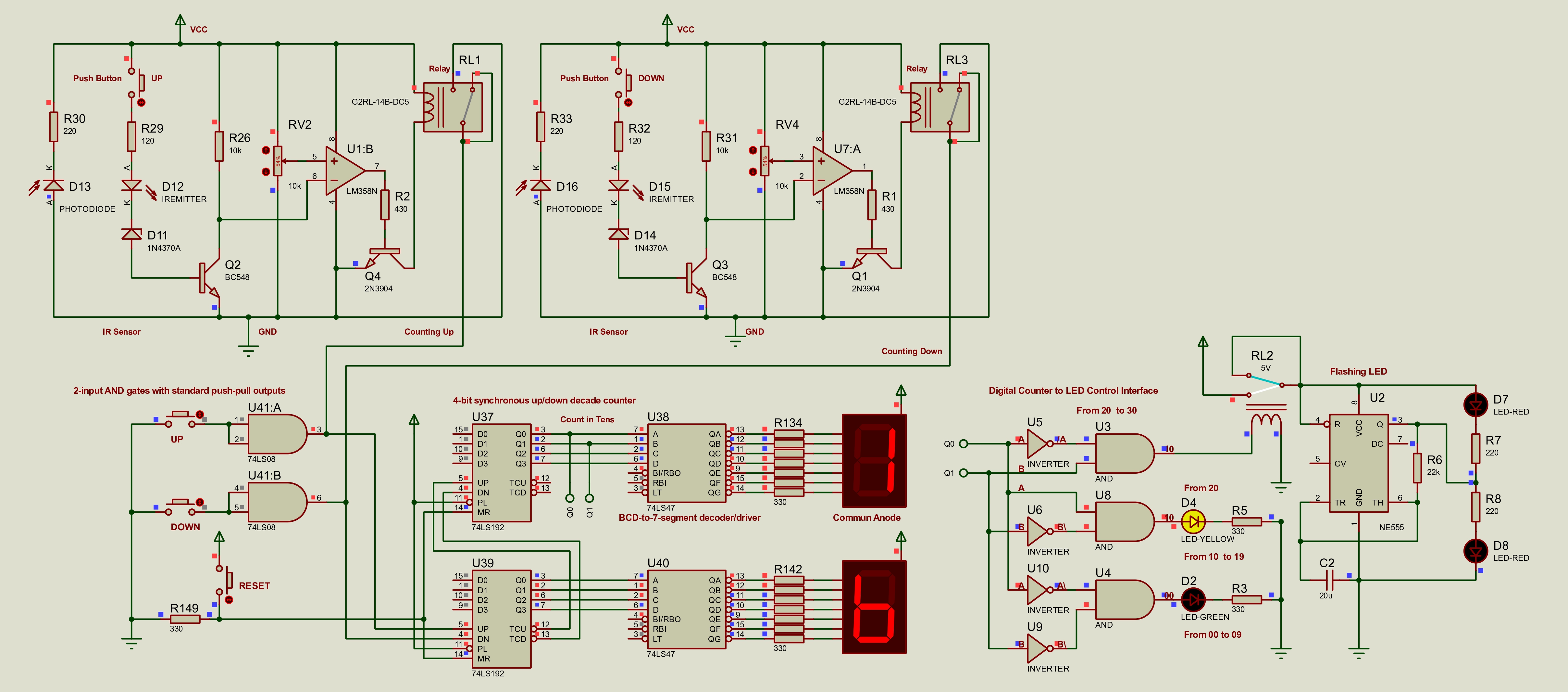
How The Three Stages Connect

This page should be used as the final integration view after each separate stage has been checked and you are ready to validate the latest 00-to-30 complete system.

Stage 1 Detector

The new IR input path uses the updated detector chain to create count-up and count-down pulses for the parking counter.

Stage 2 Counter Display

The newer Stage 2 counter chain receives the detector pulses, drives the two seven-segment displays, counts from 00 to 30, and then resets at 30 in this integrated build.

Stage 3 LED Logic

The decoded g-f-e output drives green, yellow, flashing red, and reset-at-30 behavior through logic and NE555 timing.

Visual Reference

Full Circuit Preview

Click the images to inspect the latest build, the earlier first-method build, and the mixed comparison build at full size.

Latest
Final Project Preview
The full detector, updated counter, display, LED logic, relay, and NE555 circuit in one Proteus view, configured for a 00-to-30 count with reset at 30.
Earlier
First-Method Complete Preview
The previous complete integrated simulation is still available as a legacy reference.
Compare
New Stage 1 With Old Stage 2 And 3
Use this mixed build when you want to compare the newer detector input against the earlier counter and LED-control chain inside one complete project.
System
Full System Flow
Use this polished system diagram as a quick reference while checking the Proteus file.
Related Pages

Debug By Stage