Parkade Counter
Stage 03 Files

LED Logic And NE555

This page now focuses on the Stage 3 LED-control design for the 00-to-30 maximum system: the G-F-E decoder, the relay-isolated NE555 flashing path, the reset-at-30 condition files, the Stage 2 plus Stage 3 bridge packs, and the supporting Proteus packs.

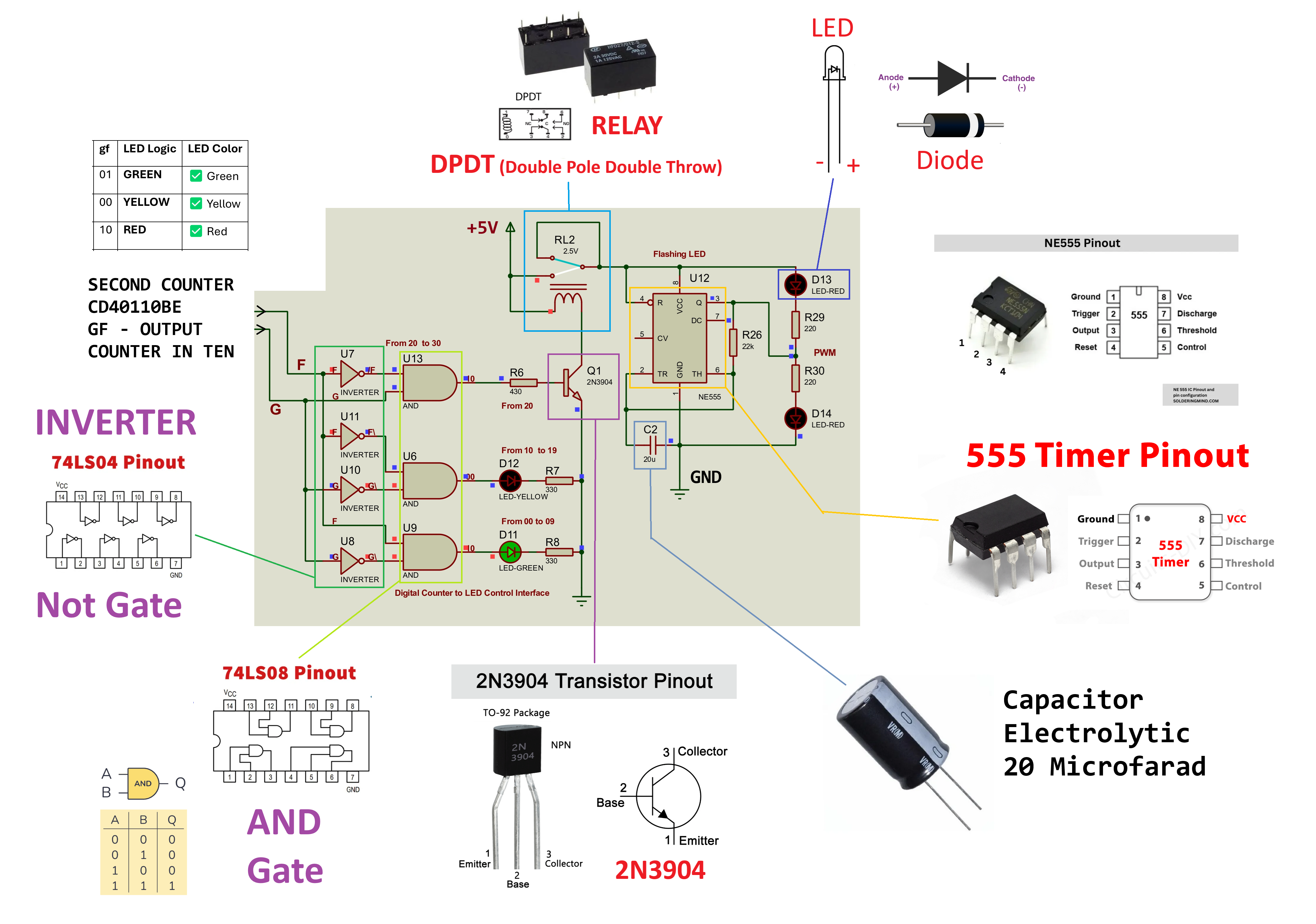
Stage 3 LED logic diagram
74LS04 74LS08 Relay Isolation NE555 Flashing Red
Stage Purpose
Decode G-F-E Into LED And Reset Output
Stage 3 converts the tens-digit segment outputs into green, yellow, flashing red, and reset behavior for the 00-to-30 maximum design. The logic gates decode the Stage 2 tens-display outputs g, f, and e, while the relay and transistor isolate the NE555 timer from the counter stage.
Do not drive the NE555 directly from the counter output. Use the transistor, relay coil, and flyback diode so the timer circuit stays isolated from the logic path.
The supplied Condition Count UP to 30 pack is the key reference for this page. It shows the three-signal decoder that keeps green on from 00 to 09, yellow on from 10 to 19, flashing red in the 20-range, and triggers reset when the count reaches 30. The newer New Project and Question8 bridge packs then show how the Stage 2 outputs feed that logic inside one file.
Detailed Theory

How Stage 3 Uses G, F, And E

Stage 3 is not separate from the counter display. In the 00-to-30 version it borrows three segment outputs from the Stage 2 tens display, specifically the g, f, and e pins from the tens CD40110 display output, then decodes those three signals into the LED and reset states.

Why G-F-E Is Used

The units digit changes from 0 to 9 every cycle, so it cannot tell the circuit whether the count is in the green, yellow, high-capacity, or reset condition. The tens digit changes only when the count passes 9, so it carries the range information Stage 3 needs.

In the supplied condition sheet, each seven-segment digit is written in gfedcba order. For the 00-to-30 build, Stage 3 uses the first three bits of that pattern: g, f, and e.

What Stage 3 Receives

When the count is 00 to 09, the tens digit is 0, so the pattern is 0111111. From that, g = 0, f = 1, and e = 1.

When the count is 10 to 19, the tens digit is 1, so the pattern is 0000110. From that, g = 0, f = 0, and e = 0.

When the count is 20 to 29, the tens digit is 2, so the pattern is 1011011. From that, g = 1, f = 0, and e = 1.

When the count reaches the 30 maximum, the tens digit is 3, so the pattern is 1001111. From that, g = 1, f = 0, and e = 0, which is used for the reset condition.

Count rangeTens digitTens pattern gfedcbagfeLogic stateOutput
00-0900111111011g f e = 0 1 1Green ON
10-1910000110000g f e = 0 0 0Yellow ON
20-2921011011101g f e = 1 0 1Flashing red path ON
30 max31001111100g f e = 1 0 0Reset ON
The supplied Condition Count UP to 30 sheet extends the old two-signal decode into a three-signal decoder. That lets the circuit distinguish tens digits 0, 1, 2, and 3 so the design can keep green, yellow, and flashing red separate while still enforcing reset at the 30 maximum.
Gate Logic

Boolean Decoder For Green, Yellow, Red, And Reset

After the tens display gives g, f, and e, the inverter and AND gates turn those three bits into one active state for the 00-to-30 design.

Equation 01
Green Output
Green is active when the tens digit is 0. In that state g = 0, f = 1, and e = 1, so the logic is Green = e AND f AND NOT g.
Count range: 00-09
Equation 02
Yellow Output
Yellow is active when the tens digit is 1. In that state g = 0, f = 0, and e = 0, so the logic is Yellow = NOT e AND NOT f AND NOT g.
Count range: 10-19
Equation 03
Flashing Red Output
The high-capacity red path is active when the tens digit is 2. In that state g = 1, f = 0, and e = 1, so the logic is Red = e AND NOT f AND g.
In the project circuit, this red output drives the relay/NE555 flashing path instead of driving only a static LED.
Equation 04
Reset At 30
The reset condition is active when the tens digit is 3. In that state g = 1, f = 0, and e = 0, so the logic is Reset = NOT e AND NOT f AND g.
Count range: 30 maximum

Role Of The 74LS04

The inverter creates the missing opposite signals, NOT g, NOT f, and NOT e. Without these inverted signals, the circuit could not separate the 0, 1, 2, and 3 tens-digit conditions needed by the 00-to-30 design.

Role Of The 74LS08

The AND gates combine the direct and inverted signals. Only one equation becomes true for the selected tens state, so only the matching LED or reset path is enabled.

High-Capacity Path

Why The NE555 And Reset Are Separate

The 20-range warning and the 30-maximum reset are not the same event. The red logic path drives the transistor and relay for the flashing warning, while the 30 condition is decoded separately to stop the count at the maximum point.

Counter Side

The Stage 2 tens counter provides the g, f, and e signals. These signals should stay as logic-level decoder inputs, not power-driver outputs.

Relay Driver Side

The red decode output for the 20-range drives a transistor, which energizes the relay coil. A flyback diode protects the transistor and logic gate from the relay coil's reverse voltage spike.

Timer Side

The relay switches the NE555 flashing circuit into the red LED path. This gives a visible warning while keeping the timer electrically separated from the counter output.

Reset Side

The 30-maximum condition is decoded separately from the red flasher path. That reset line returns the system to the starting count instead of leaving the display beyond the project limit.

Stage 3 Documents

PDF References

These PDFs are the written references for the Stage 3 LED decode, the G-F-E count-up-to-30 condition, and the full project partition.

Document 01
LED Logic Explanation
Explanation sheet for the complete BCD counter display and LED-status logic chain.
Document 02
Project Partition
Project partition document covering the stage breakdown and final simulation context.
Document 03
Condition Count Up To 30
Supplied Stage 3 reference sheet showing the G-F-E decoder, the flashing-red path, and the reset-at-30 maximum condition.
Document 04
Final Simulation Notes
Additional final simulation reference supplied with the Proteus and PDF material.
Document 05
New Project - Stage 2 And Stage 3
Combined reference pack showing how the Stage 2 counter outputs feed the Stage 3 LED control interface inside one project.
Document 06
Question8 - New Stage 2 And Stage 3
Updated combined reference pack showing the new Stage 2 counter section and new Stage 3 LED logic working together inside one project.
Stage 3 Proteus Pack

Logic And Timing Files

These are the Stage 3 Proteus project files and exported PDFs from the supplied Proteus folder, with the new G-F-E count-up-to-30 condition pack and the new Stage 2 plus Stage 3 bridge projects added to the LED section.

Logic 01
Condition Count Up To 30
Main Stage 3 condition package for the 00-to-30 maximum design, showing the G-F-E decoder, flashing-red warning path, and reset-at-30 logic.
Logic 02
LED Binary Control
Status LED decode project package for the logic path that decides green, yellow, and red output behavior.
Logic 03
First Method LED Logic
First-method LED logic simulation package used to validate the final status behavior.
Bridge 01
New Project - Stage 2 And Stage 3
Combined project linking the digital counter outputs to the LED control interface so the Stage 2 to Stage 3 handoff can be checked in one file.
Bridge 02
Question8 - New Stage 2 And Stage 3
Updated bridge project linking the newer Stage 2 counter section to the newer Stage 3 LED logic so both parts can be checked together.
Timer 01
NE555 Flashing Timer
Standalone NE555 timing simulation used to validate the flashing red warning output before final integration.
Status Behavior

Decoded LED States

Use these state references while checking the logic files, the explanation PDF, and the new count-up-to-30 condition sheet.

Green State

Count 00 to 09. Normal available-parking state with gfe = 011.

Yellow State

Count 10 to 19. Warning state as the parkade approaches capacity with gfe = 000.

Flashing Red State

Count 20 to 29. The relay enables the NE555 timer to drive the high-capacity flashing warning with gfe = 101.

Reset At 30

Count 30 maximum. The reset path turns on at gfe = 100 so the system returns to the allowed range.

Visual References

Stage 3 Images

These condition sheets and stage images are preserved from the supplied image folders, including the new G-F-E count-up-to-30 reference, the new Stage 2 plus Stage 3 bridge previews, the extra relay and flyback-diode reference drawings, the added logic-family comparison image, and the new 7408 AND-gate pinout reference.

Condition
Count Up To 30
Main Stage 3 visual reference for the G-F-E LED decoder, flashing-red path, and reset-at-30 logic.
Bridge
Stage 2 + Stage 3
Combined reference showing the counter display handoff into the LED control interface.
Bridge 02
Question8 Preview
Updated bridge reference for the newer Stage 2 and Stage 3 handoff.
Stage 3
Part 3 Sheet
Large-format LED logic reference image from the high-quality pack.
Condition
Green LED
Reference for the normal available-parking status.
Condition
Yellow LED
Reference for the warning status before capacity is full.
Condition
Red LED
Reference for the full-capacity flashing red output.
Relay
DPDT Contact Symbol
Quick contact diagram for understanding the relay poles used in the red-warning switching path.
Relay
Relay Package View
Physical relay outline and contact-state drawing for matching the hardware package to the switching diagram.
Driver
Relay Driver Schematic
Reference driver stage showing the transistor, resistor, relay coil, and flyback diode arrangement.
Protection
Flyback Diode Placement
Extra relay-coil protection reference for placing the diode correctly across the coil terminals.
Logic Family
4000-Series CMOS
General logic-family comparison image for the wider CMOS 4000-series, preserved next to the TTL gate references used on the Stage 3 page.
Logic Gate
7408 AND Gate Pinout
Pin-level AND-gate reference image for the 7408 family, kept beside the Stage 3 TTL logic material.
Complete
Completed Simulation
Final reference image for the complete status logic path.
Proteus
Build Screenshot
Supporting Proteus screenshot from the supplied file bundle.
Stage Links

Review The Full Chain