Stage Purpose
Detect Entry And Exit Pulses
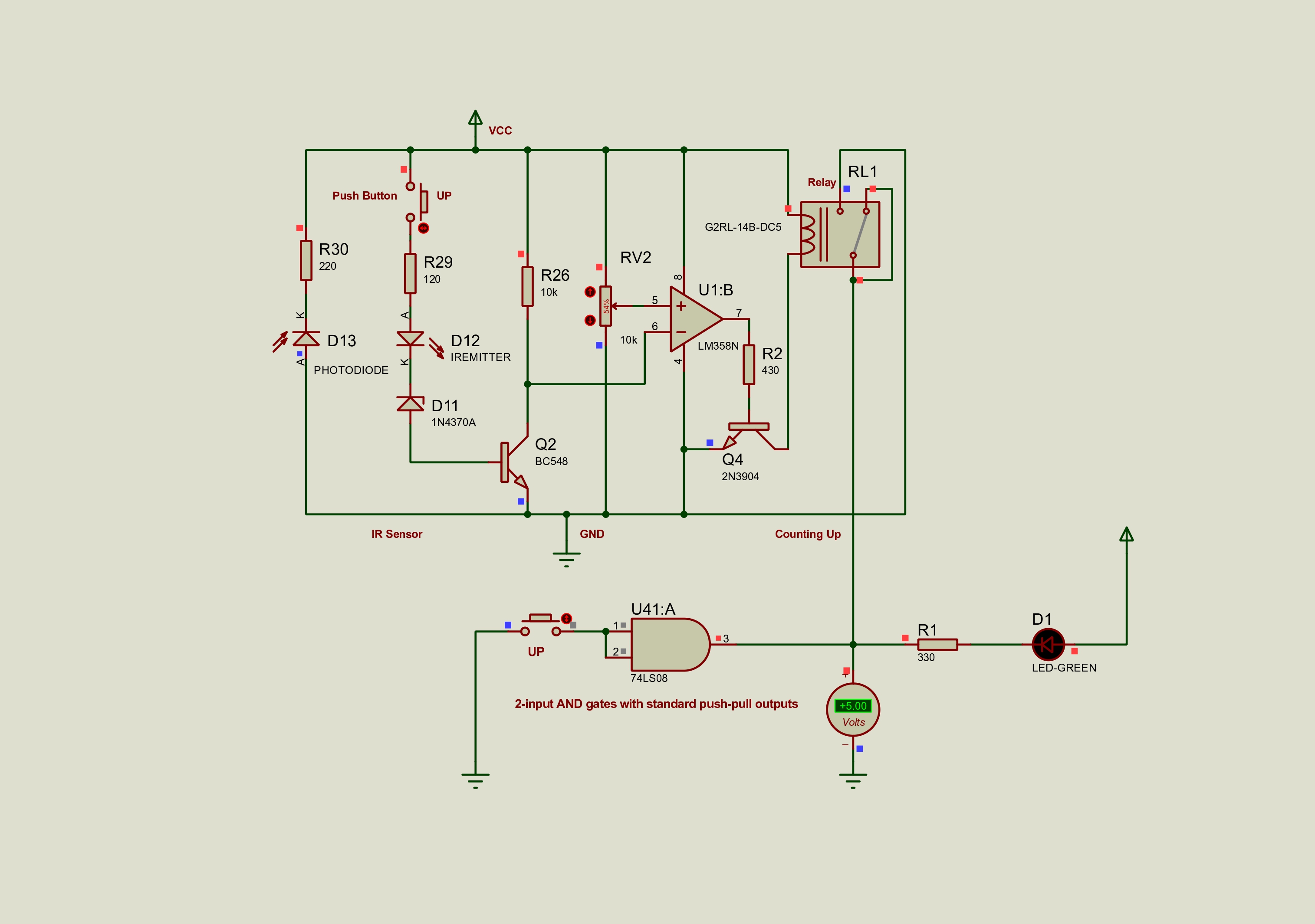
Stage 1 turns vehicle movement at the entry and exit paths into clean count-up and count-down signals. In hardware this is built around IR sensor modules; in Proteus it is represented with emitter and photodiode parts because the full module is not always available in the education library. The Question7 pack shows the newer LM358N and relay-conditioned input path, while IR Hamzi and IR Sensor and NE555 show additional detector variants built around NE555 timing and output conditioning.
Proteus rebuild note: use IREMITTER plus PHOTODIODE, then condition the signal before feeding the counter stage. Compare Question7 for LM358N plus relay handling, IR Hamzi for the ADC and PWM-oriented detector path, and IR Sensor and NE555 for the simpler sensor-to-timer version.
Stage 1 Resource Pack
Proteus Files And Exports
These are the detector files from the supplied Proteus folder, grouped so the project file, PDF, and preview image are not separated across the archive, with Question7 first and the two additional Stage 1 variants listed immediately after it.
Detector 01
Question7 - New IR Input
New Stage 1 IR input package showing the updated detector chain with LM358N conditioning and relay output handling.
Detector 02
IR Hamzi - Stage 1 Version 2
Alternative Stage 1 detector version built around the IR emitter and photodiode front end, transistor switching, ADC handoff, and NE555 timer or PWM output conditioning.
Detector 03
IR Sensor And NE555 - Stage 1 Version 3
Simplified Stage 1 detector version that couples the IR sensor front end directly into a NE555 timing and output section for signal verification.
Detector 04
IR Sensors Package
Main Stage 1 IR sensor simulation package with the Proteus project file, exported PDF, and preview image.
Detector 05
2 IR Checkpoint
Supporting two-IR detector checkpoint used for validating the entry and exit optical paths before connecting the counter stage.
Detector 06
Detector Diagram Sheet
Main Stage 1 diagram and high-quality Part 1 sheet for visual comparison while wiring the input and output detector channels.
Visual References
Detector Images
Click any image to inspect it in the site lightbox. The detector gallery now includes the main Proteus previews, the added new input or exit circuit screenshots and hardware-setup references, and the TCRT5000 module images from the earlier high-quality pack.
New IR
Question7 Preview
Updated detector input path with LM358N conditioning and relay interface.
Version 2
IR Hamzi Preview
Alternative detector variant with IR front end, transistor switching, ADC handoff, and NE555 timing output.
Version 3
IR Sensor And NE555 Preview
Simplified detector variant that couples the IR front end directly into a NE555 output path.
Stage 1
Detector Diagram
The polished diagram view used across the site.
Proteus
2 IR Preview
Checkpoint preview for the two optical paths.
New IR
New IR Circuit
Fresh reference image for the newer Stage 1 detector input or exit circuit path.
Screenshot
IR Circuit Screenshot 1
Detailed screenshot from the newer detector input or exit circuit set.
Components
Recent IR Components
Reference view of the newer detector components used around the entry and exit circuit path.
Screenshot
IR Circuit Screenshot 2
Extra visual checkpoint from the newer Stage 1 detector circuit set.
Close-Up
IR Circuit Close-Up
Tighter screenshot view kept with the new input or exit circuit references.
Hardware
IR Hardware Setup
Physical setup reference for the newer detector hardware arrangement.
Setup
IR Hardware Simulation Setup
Combined setup view connecting the newer detector hardware arrangement to its simulation layout.
Compare
IR Components Simulation-Hardware
Reference image linking the newer detector component set to both simulation and hardware context.
Hardware
IR Module Reference
Reference image for the physical IR detector part.
TCRT5000
Infrared Sensor Module
Hardware reference for the TCRT5000 IR module used for vehicle detection in Stage 1.
Hardware
Sensor Module View
Additional module view for identifying the IR emitter, receiver, and board layout.
TCRT5000
Product Reference
Reference image for the physical TCRT5000 infrared sensor module used in the Stage 1 detector.
Next Stage
Continue The Build
Stage 02
Counter And Display
Move from detector pulses to the CD40110BE counter and seven-segment display chain.
Complete
Full Circuit
Open the integrated Proteus simulation that combines the new IR input, newer Stage 2 chain, and Stage 3 logic.
Summary
All Stages
Return to the original three-stage summary page.
Archive
Project Archive
Open the full PDF, Proteus, and image archive.