Parkade Counter
Reference Hub

Component Formula Sheets

Use this page as the research desk for the parts mentioned across the website. Each card points back to the local stage pages, then out to official manufacturer pages, datasheet PDFs, or reference tools that help you verify pinouts, formulas, limits, and selection rules, including the seven-segment variants, the support hardware in the BOM, and the later-added input or exit build references.

Full signal flow diagram for the automated parkade counter
Stage 1 Stage 2 Stage 3 Datasheets Formula Checks Official Sources
The page focuses on the real hardware families used in the build, the Proteus-only substitute pair used in Stage 1, and the support hardware and passive groups that keep the circuit stable, readable, and serviceable.
How To Use It
Fast Path From Site Page To Manufacturer Sheet
Start with the local page links if you want the project context first. Use the official page links when you need current manufacturer information, and open the PDF links when you need the actual datasheet tables, formulas, pinouts, or timing curves.
Default scope for this hub: the main hardware parts on the site, the integrated seven-segment module reference preserved in the gallery, and the BOM support items that matter during the real hardware build, including breadboards, jumpers, sockets, and the split capacitor references.
22 component families local cross-links official product pages pdf datasheets
Universal Checks

Core Formulas Used Repeatedly

These are the quick equations and checks that appear again and again while building the detector, display, and LED output stages.

R = (VS - VF) / I
LED Resistor

Use this for the seven-segment display resistors and the green, yellow, and red status LEDs.

RB ~= (VDRIVE - 0.7) / (IC / 10)
Transistor Switch Bias

A good first-pass base resistor estimate for the 2N3904 or BC548 when driving a relay or shaping a logic pulse.

f ~= 1.44 / ((RA + 2RB) C)
NE555 Astable

The main timing relationship for the flashing red output path.

tau = R x C
RC Time Constant

Useful for reset clean-up, decoupling intuition, and timing behavior checks around sensors and counters.

Stage 1

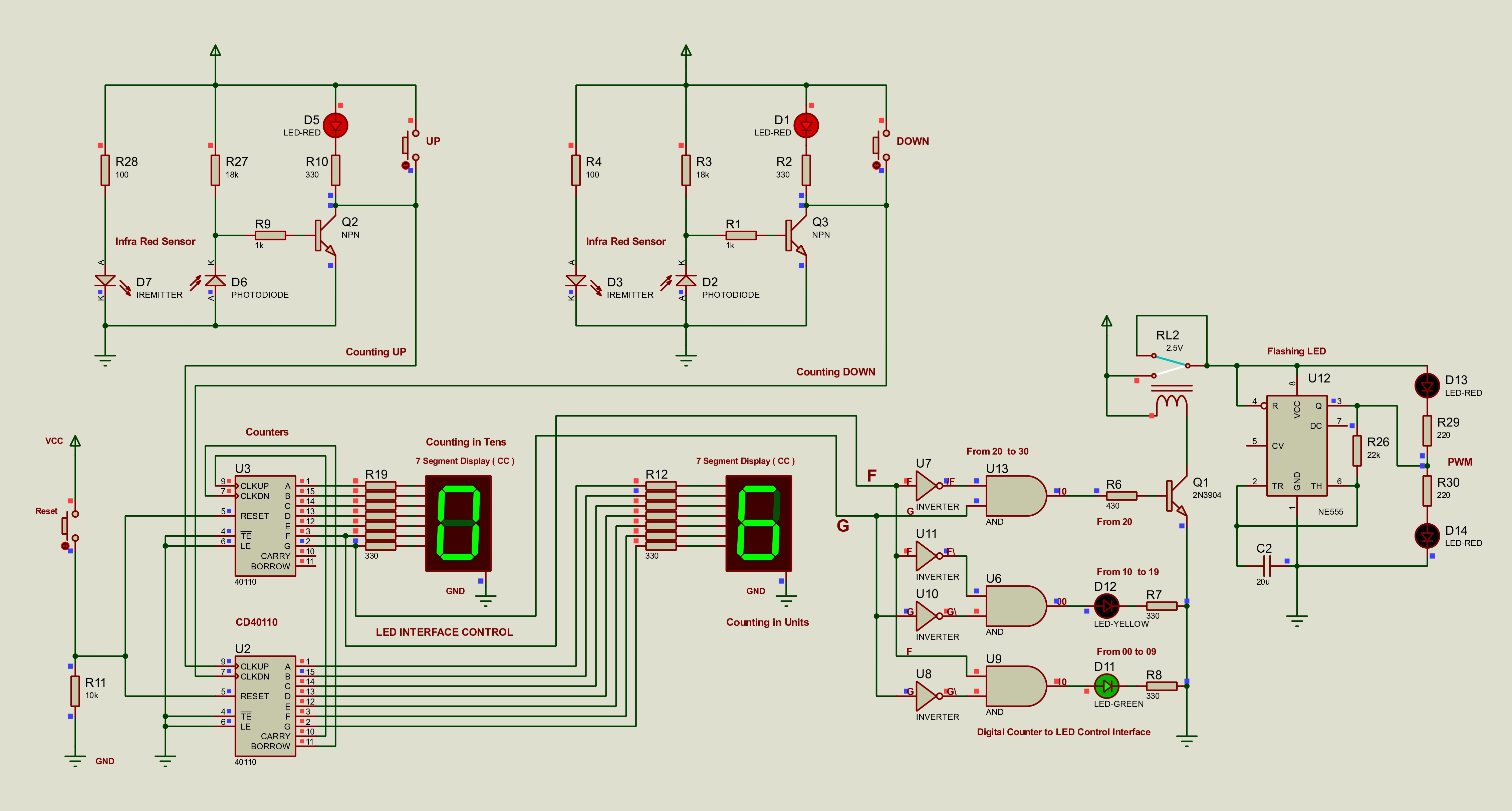
Detector And Input Conditioning

Sensor, amplifier, and switch parts used to turn entry and exit movement into usable count-up and count-down pulses.

Stage 2

Counting And Display

The counter and display references used to drive the two-digit occupancy display, including the common-anode and common-cathode comparison variants and the integrated resistor module reference preserved in the gallery.

Stage 3

Logic, Timing, And Output Drive

The logic gates, timer, relay, diode, and indicator parts used to translate the count state into green, yellow, and flashing red outputs.

Support Families

Passives And Build Helpers

These cards cover the passive groups and the physical build helpers that appear repeatedly in the BOM, the hardware photos, and the reference pages.

Visual Reference

Push Button Pinout

This hardware pinout belongs with the component-reference material, not the Proteus search page. Use it when wiring the real 4-pin tactile buttons for count-up, count-down, and reset.

Button
Push Button Pinout
Hardware reference for the 4-pin tactile push buttons used for manual count and reset control.
Continue

Related Pages