For CPUT students only. Do not share outside the institution. Never click Check for Updates after installation, because the license copy is version-locked and can break when updated.
Download And Install
1Extract the ZIP archive to a local folder before running setup.
2Launch setup.exe and complete the installer.
3Open license.txt and copy the provided license key.
4Paste the key when Proteus starts, or use Help -> Licence Manager if the prompt does not appear.
5Create a new project from File -> New Project and start by validating each stage independently.
6Keep the detector, counter, and status-control stages separate until each one behaves correctly on its own.
!Do not run Check for Updates. This installation is version-locked.
Reference Set
Local Support Material
These project files sit inside the site folder now, so the simulation notes can be opened side by side with the schematic diagrams while rebuilding the circuit.
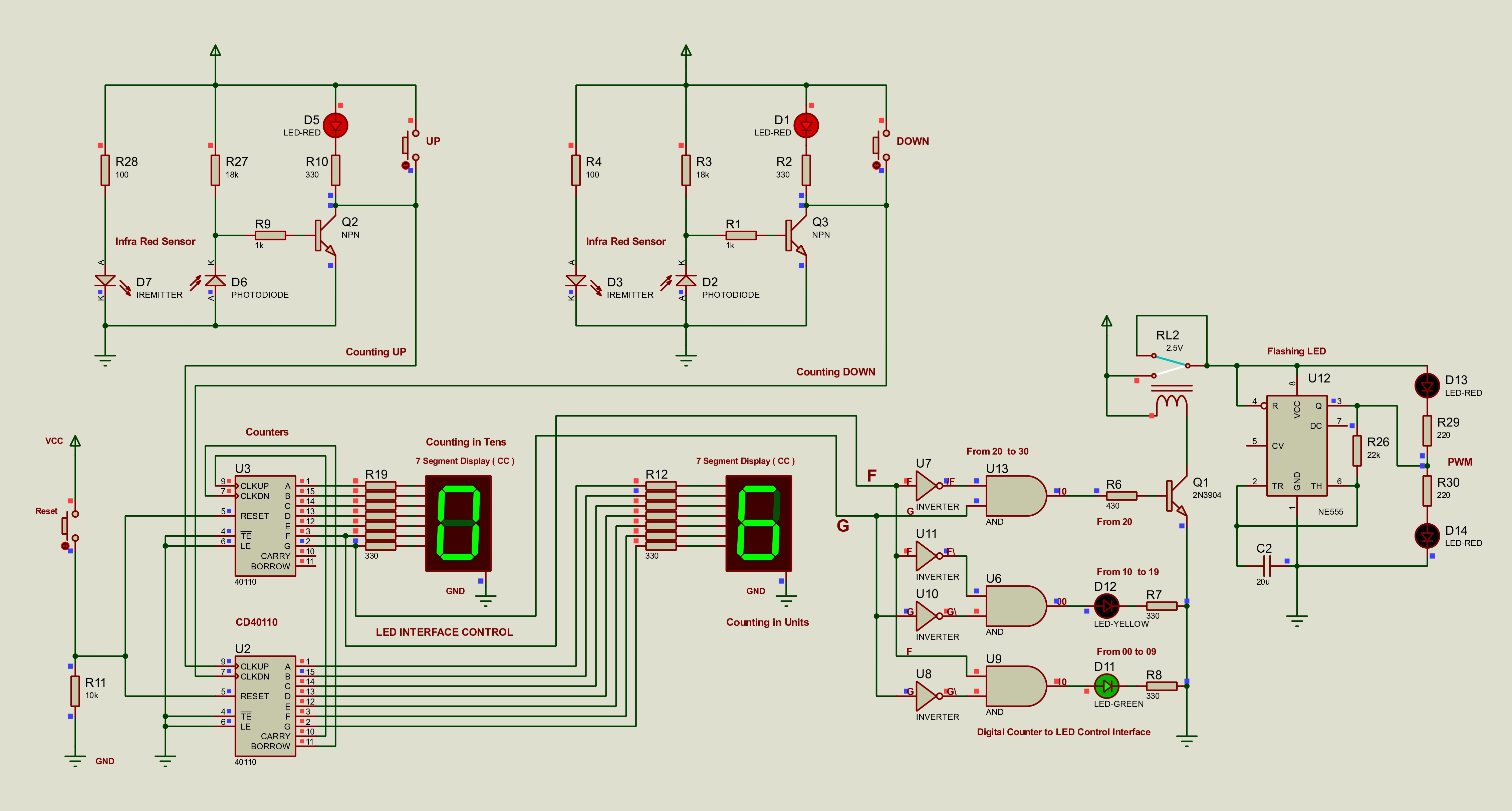
Use the high-resolution full-system schematic as the top-level Proteus reference.
Component Search Mapping
| Proteus search term | Real component | Notes |
|---|---|---|
| 40110 | CD40110BE | Search exactly 40110 |
| 7SEG-COM-CAT-GRN | Common cathode display | Use CAT, not CAA |
| IREMITTER + PHOTODIODE | TCRT5000 equivalent | Education license workaround |
| 7408 | 74LS08 quad AND gate | Also appears as [7408] |
| INVERTER | 74LS04 hex inverter | Generic inverter maps correctly |
| NE555 | NE555 timer | 22k ohm and 20uF gives roughly 1Hz |
| G2RL-14-DC5 | DPDT relay 5V | Any 5V DPDT relay works in hardware |
| 2N3904 | 2N3904 transistor | BC548 can be used as an alternate |
| 1N4148 | 1N4148 diode | Use across the relay coil |
Device Library
These names are the ones that matter in the Proteus library for this project:
1N41482N3904BC548
401107SEG-COM-CAT-GRN7408
INVERTERBUTTONCAP
RESIREMITTERPHOTODIODE
LED-GREENLED-YELLOWLED-RED
G2RL-14-DC5NE555NPN
Common cathode displays only. Do not use common anode displays for the CD40110BE stage.
Each display segment needs its own 330 ohm current-limiting resistor.
Call Communica ahead if you need a physical CD40110BE for the final build.
Visual Checks
Library And Button References
Use these image references when searching the Proteus library and matching the Proteus device names to the real parts used across the project.
Proteus
Raw Search Capture
Original library screenshot showing the search results and selected device names used in the first complete rebuild.
Proteus
Selected Components List
Cleaned reference image showing the exact Proteus search names and the matching hardware parts used in the first complete circuit.
Proteus
Components Table
Structured table version of the component list used for the first complete Proteus build.
Actual Proteus Code
Proteus Project Downloads
These are the actual Proteus 8 Professional project files from the supplied Proteus folder. Download the .pdsprj files when you need to open or edit the simulations in Proteus.
Local File Bundle
Bundled Proteus Resources
The original site only summarized the Proteus workflow. The missing project files are now linked directly here, with the full archive page holding the larger reference pack, including the comparison complete-system build that mixes the new Stage 1 with the older Stage 2 and Stage 3 sections.