How The Circuit Works
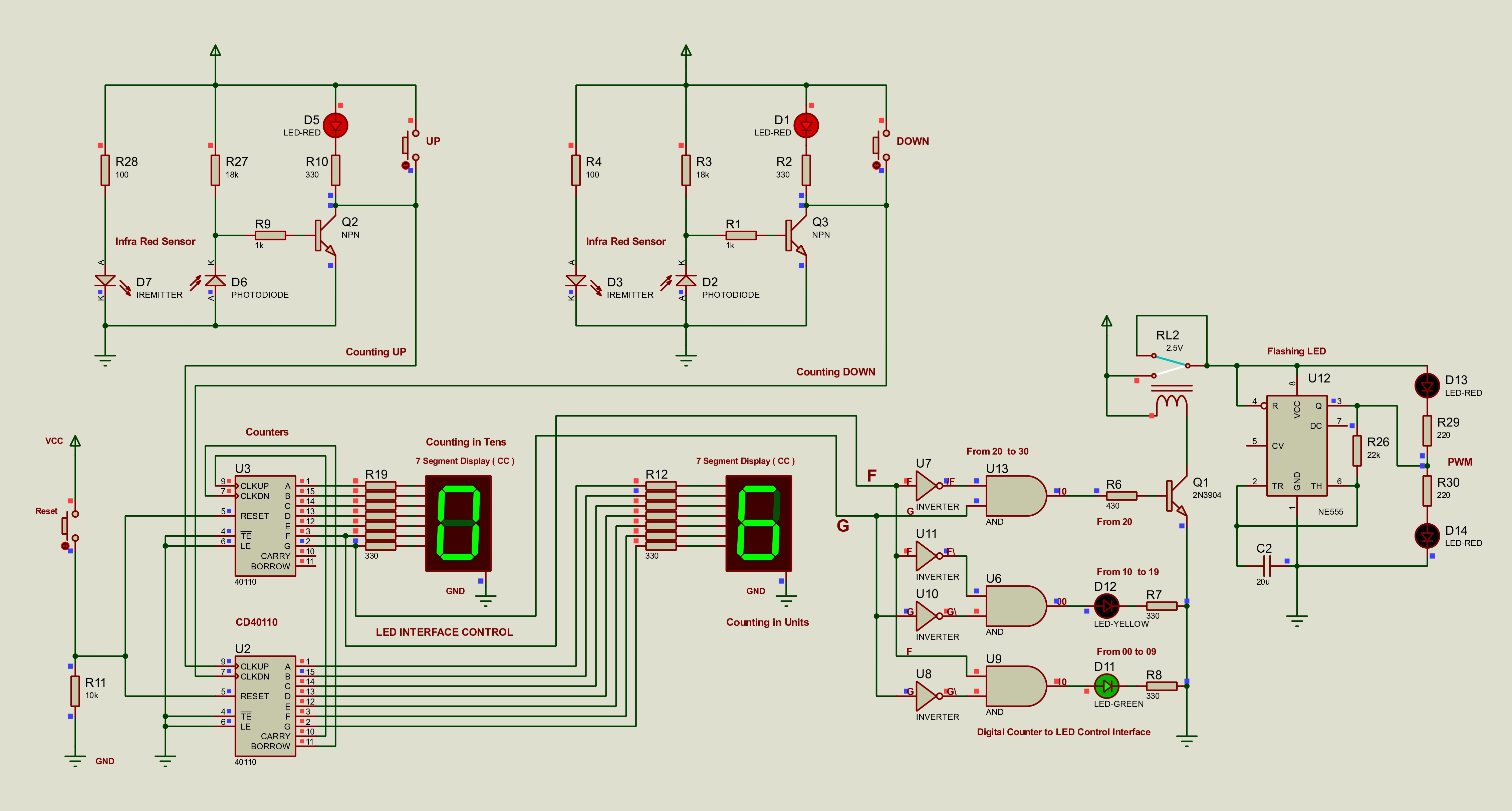
The system is built stage by stage: sensor detection creates clean logic pulses, the counter stage tracks the occupancy value, and the status stage translates the count into green, yellow, flashing red, and reset-at-30 output states.
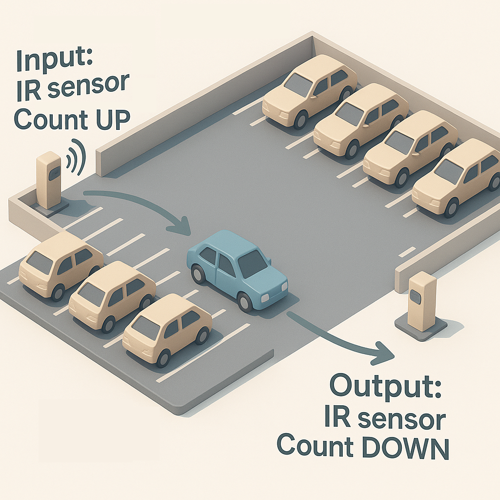
Input Detection
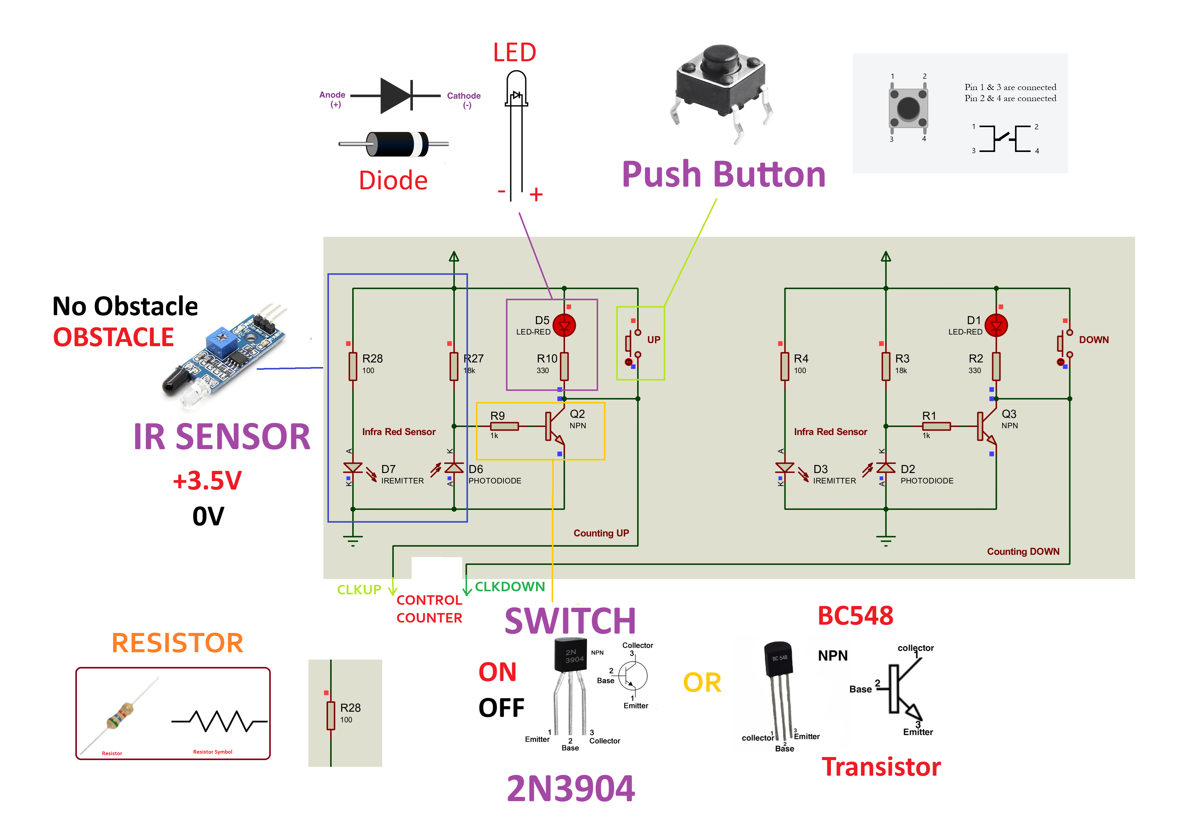
Two IR sensor paths at the entry and exit points produce the count-up and count-down pulses. In hardware the TCRT5000 module is used; in Proteus the equivalent pair is IREMITTER plus PHOTODIODE.
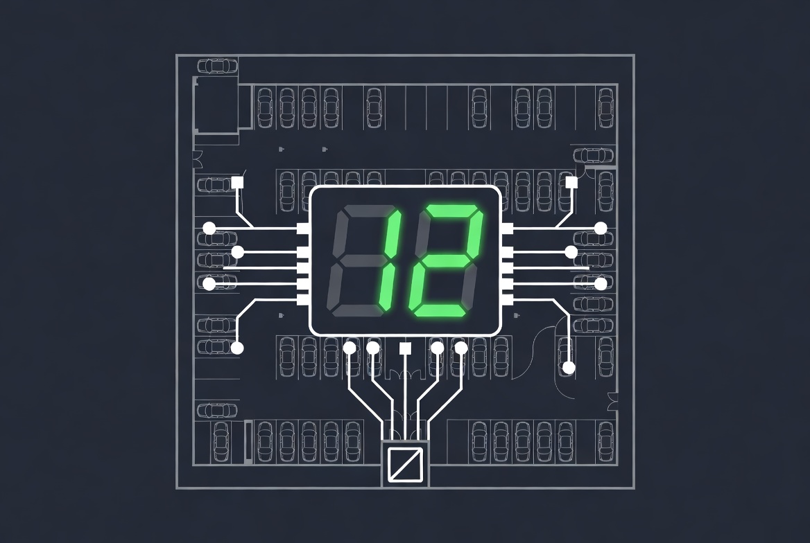
Counting Logic
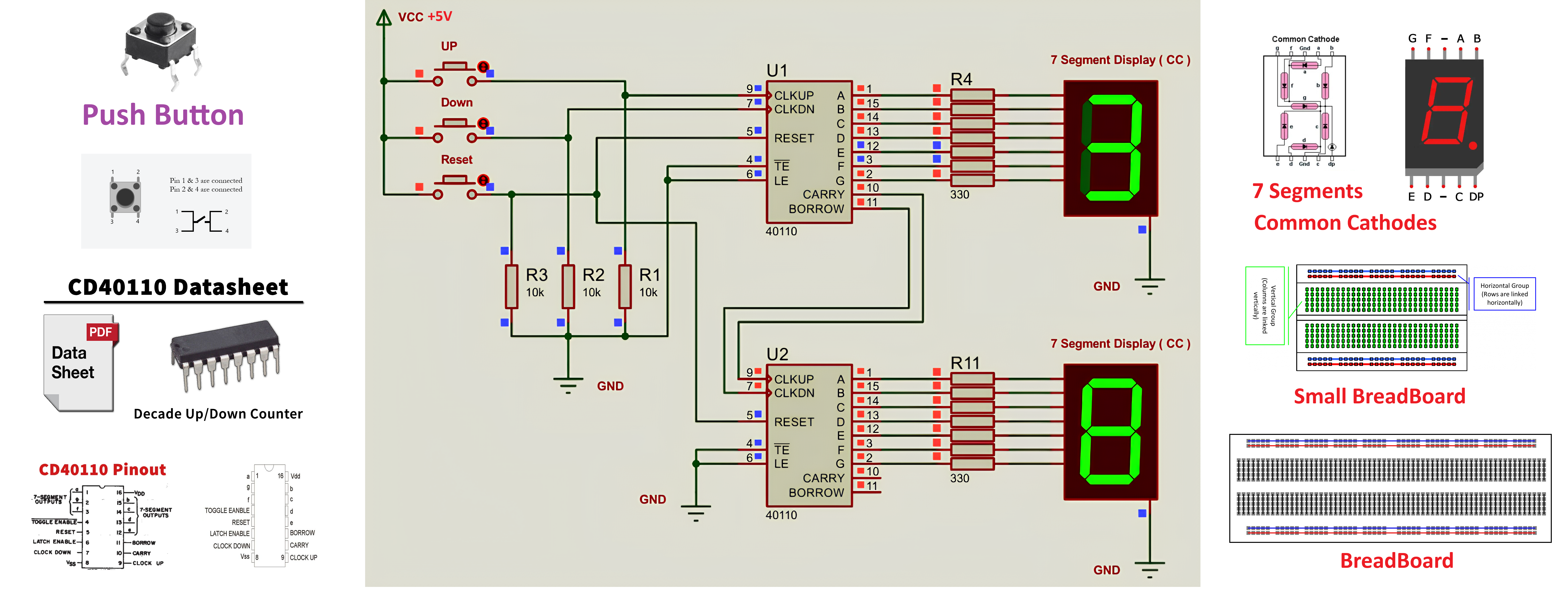
The conditioned pulses feed cascaded CD40110BE counters. Carry and borrow chaining allows the design to show vehicle count across two seven-segment displays while staying in pure hardware.
Status Decoding
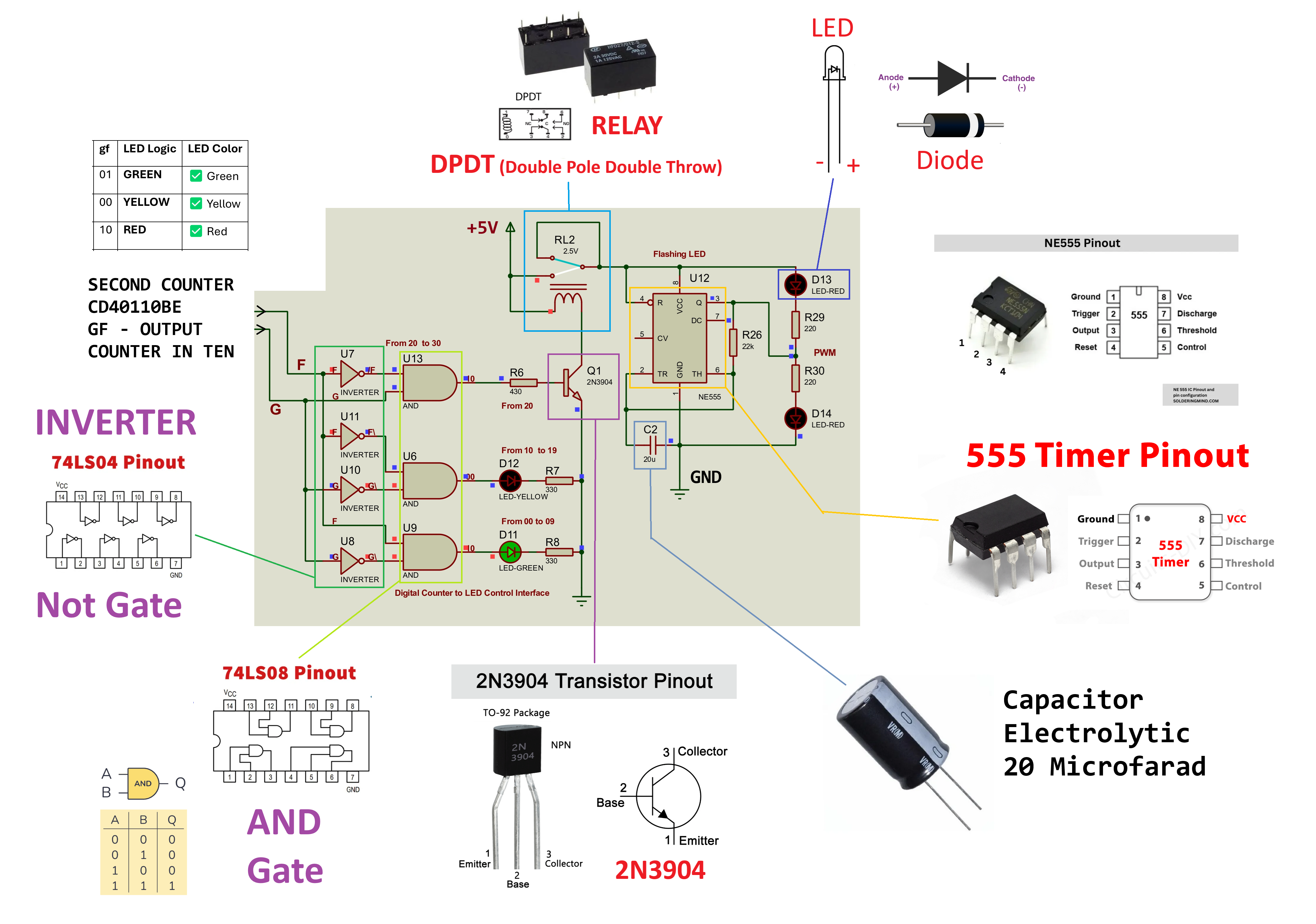
Stage 3 reads the tens-display outputs g, f, and e. Green covers 00-09, yellow covers 10-19, the 20-29 range switches an isolated NE555 flashing red path, and 30 triggers the reset condition.
Build Discipline
The assignment requires each stage to be designed and tested independently first. That structure is reflected across the diagrams, BOM, tutorials, and PDF documents in this site.